Engineering Judgments for Fire Resistance Rated Assemblies
In previous articles, the need for various fire-resistance rated walls, barriers, floors, and ceilings was discussed along with examples of when they are needed. When fire resistance rated assemblies are needed, they are designed or selected in any of the following ways:
- By following a prescriptive design fashioned in Chapter 7 of the International Building Code (IBC)
- By following prescriptive designs outlined in other approved sources such as the International Existing Building Code
- By calculating the fire resistance rating of an assembly via procedures outlined in Chapter 7 of the IBC
- By utilizing a design that has been tested to a design standard such as ASTM E119 and has been published by an approved testing agency
- Performing an engineering analysis based on the fire resistance ratings of multiple elements, components, or assemblies
- Alternative means and methods as permitted by Chapter 1 of the IBC
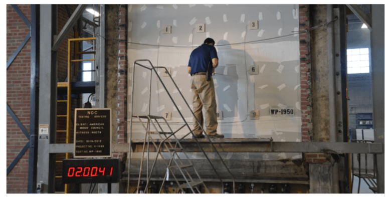
Figure 1: Preparation of a Full Scale Fire Assembly for Testing
Within the IBC, employing fire resistance assemblies utilizing methods outlined in one through four above does not necessarily require the involvement of a specialist, such as a licensed fire protection engineer. The architect, structural engineer, or other designer of record can utilize these quoted resources and find a suitable assembly for their design purposes. However, sometimes a typical design professional is uncomfortable doing so, and may enlist the help of a specialist.
On the other hand, employing methods five or six above almost always involves consultation with a fire protection engineer. The fire protection engineer may also utilize methods one through four, in addition to five and six, to come up with a suitable design. The reasons why such consultation may be necessary or desired includes, but is not limited to the following:
- A prescriptive assembly cannot be found or is not appropriate for the construction circumstances of the building
- A tested assembly, published through an approved agency or source, is not the exact assembly that is needed for construction
- Third party products, such as spray applied fireproofing, may be available for usage and have their own testing data that must be applied to specific field conditions
- Dimensional constraints may prevent the full construction of an approved assembly
- The authority having jurisdiction may request third party assistance in approving an assembly
When a fire protection engineer is engaged in an effort to find a suitable assembly, it is typically referred to as an “engineering judgment” or “EJ.” Fire protection engineers are often retained very quickly to find a suitable assembly, as it’s a critical element in construction that may be preventing the completion of other construction activities.
How to Perform an Engineering Judgment
Starting out with an engineering judgment involves determining why a fire resistive rated assembly is required, what the required rating is, and what the construction constraints are. It is also essential to know why the assistance of a fire protection engineer is being sought out, and to find out what methods or construction details were submitted and rejected, and the reasons for these. During this period, other information, such as design drawings, construction submittals, product submittals, and other information is collected.
After the necessary information is gathered, the fire protection engineer applies techniques one through four to see how close of an assembly may be obtained utilizing those methods. After this, detailed fire protection engineering techniques are employed to find a suitable assembly. Often, design iteration is required, with calculations, for formulate a solution. The final solution may involve multiple materials sandwiched together, with their respective fire resistance ratings determined and added together. However, there are strict rules with regards to how fire ratings may be tabulated, and construction requirements for when membranes or other coverings may be counted towards a fire resistance rating. For example, 2×4 studs alone cannot be counted unless they are encapsulated by drywall on both sides.
A fire protection engineer (FPE) performing an engineering judgment must also be versed in structural engineering, architectural engineering, and construction. Most fire resistant building construction must meet structural performance standards. The FPE must also understand its use in the project and how the contractor intends on constructing it. Often, the need for an alternative assembly via Engineering Judgment, is due to contractor limitations arising from specification errors or scheduling conflicts. The FPE must keep both the needs of the client and the requirements of the assembly in mind. For these reasons, engineering judgments are normally performed by fire protection engineers with heavy experience and multidisciplinary engineering and trade knowledge.
Example of an Engineering Judgment
A description of an engineering judgment is useful, but a full example is necessary to capture the essence of one. What follows is an actual engineering judgment produced for a client, with identifying details removed.
Mr. XXX,
Pursuant to your request, this is an engineering judgment to determine an approach to fire resistant rated assemblies in accordance with Section 703.3(4) and 703.3(5). This approach uses both an engineering judgment and an alternative means and methods in determining the appropriate ways to protect assemblies to obtain the desired fire resistance rating.
Required Rated Assemblies
Within the basement of the subject property, there is a Group S-2 fire area that is separated from the remainder of the building with 2 hour rated walls, ceiling, and columns. The building construction type is Type VB with no sprinklers. The walls are to be fire resistance rated with prescriptive fire resistance rating Item 14-1.5. The ceiling is to be protected via UL Design L556, which is a combination of wood flooring, wood trusses, gypsum wallboard, and rigid furring channels. The subject of this engineering judgment are the steel columns and the dropped beams which support the floor truss assembly. The columns are 5 inch round columns with 0.25 inch wall thickness. The dropped beams are W12x35 beams. All assemblies, including the supporting construction, must be rated to two hours.
Use of FlameOff Intumescent Paint
ICC-ES Evaluation Report ESR-3874 states that FlameOff is to only be used in buildings of Type I and II construction. FlameOff has several other ICC-ES reports that do not list this description. Typically, steel construction is found within buildings of Type I and II construction. Therefore, it is assumed that, since none of the other ICC reports specify this limitation, ESR-3874 listed it because Type I and II construction would be its most common application. That said, as long as structural steel with intumescent paint is in contact or proximity to similarly rated assemblies, it is the same condition as being installed within Type I or II construction.
Determination of FlameOff Intumescent Coating Thicknesses
The listed reports from FlameOff do not directly list the required spray thicknesses to achieve the desired two hour rating for the assemblies described above.
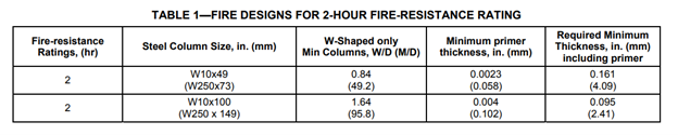
ICC-ES ESL 1162 describes two 2 hour rated steel columns, W10x49 and W10x100, which have W/D ratios of 0.84 and 1.64, respectively. These are the minimum W/D ratios that the report is applicable for. The W12x35 beam has a W/D ratio of 0.7. Table 1 shows the tested columns.
ICC-ES ESL-1190 specifies some restrained and unrestrained coating thickness requirements for beams. They are presented below as Table 1.
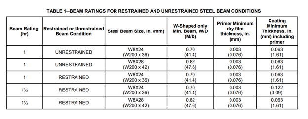
The W8x24 beam thickness has the minimum W/D ratio to apply to the W12x35 beam; however, it is only for a 1.5 hour restrained assembly, and a 2 hour rating is required. A 122 mil coating thickness would be required on the W12x35 beam for a 1.5 hour, restrained, rating. Since columns are subjected to more severe exposures than beams (four side heating and the buckling failure limit state), the required thickness for the W12x35 beam is probably greater than 122 mils but not quite 161 mils.
For the 5 inch column, ICC-ES ESL-1157 lists direct data for a 6 inch round column with a 0.5 inch thickness. For the 6 inch column, A/P=0.435, 76 mils of paint is required for a 1 hour fire resistance rating. The 5 x 0.25 column has an A/P=0.22 and a W/D of 0.76.
Since none of the data is directly applicable, a means of interpolating or extrapolating the data must be performed to determine the correct thickness of FlameOff to apply.
Data Interpolation and Extrapolation
Equation 7-13 within Section 722.5.1.3 can be used to relate different thicknesses of spray fire material, different W/D ratios, and different fire resistant ratings. After this equation is presented, the IBC specifically states that intumescent coatings shall be determined on the basis of fire resistance tests in accordance with Section 703.2. This approach still adheres to that, because we are using experimental results to derive material constants, and are then using those material constants to calculate a different thickness for a different fire resistance rating.
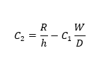
Equation 7-13 is as:
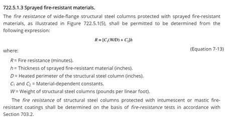
Rearranging Equation 7-13, C2 can be solved for. With two fire tests, the substitution method can be used to solve for C1 and C2. Once these material constants are known, different value of h can be solved by solving for which value of h makes R equal to 120 minutes, or 2 hours.
The test data for the W8x24 beams in the table above were used to derive the material constants C1 and C2 using the substitution method. The two equations are not linear, so an exact solution was not derived, but C1 and C2 were found to be equal to -8000 and 6400, respectively. The W/D ratio of the beam we are solving for, W12x35, is also 0.7. A value of 150 mils is required for a fire resistance rating of 120 minutes, as:
![]()
Due to the uncertainty of the data and approach, a 33 percent safety factor shall be applied. Thus, the required thickness of FlameOff for the W12x35 beam is 200 mils.
The same approach was used for the columns, but the test data from ESL-1162 was used. The material constants in this approach were found to be, C1 and C2, 647 and 202. A thickness of 175 mils is required to achieve the 120 minute rating with the W/D ratio of 0.76 for the circular column. Adding a safety factor and keeping in mind the value attained for the previous beam, the required thickness shall be 200 mils.
Conclusion
The interpolation and extrapolation of the data was based on actual testing using a formula found within the IBC. In the beam’s case, the required hourly rating was higher, and the required thickness was higher than the published test data, as expected. In the column’s case, the W/D ratio was lower with the hourly rating the same, and the required thickness was higher, as expected. Safety factors have been applied and the required thickness has been adjusted to be the same for the columns and beams so as to minimize application errors.
The referenced ICC-ER Reports have been attached as a reference.
-John P. Stoppi Jr., PE, FPE is a seasoned fire protection and architectural engineer and is also a certified building inspector. He has extensive experience writing engineering judgments for fire resistant rated assemblies.