Figure 1: Fire Sprinkler Discharging
Previously, I have written when an automatic fire sprinkler system is required. Even when fire sprinklers are not required, they are often installed in buildings to protect life and property. NFPA 13: Standard for the Installation of Sprinkler Systems defines and prescribes requirements for many different types of sprinkler systems. For example, there are wet type, dry type, preaction, deluge, and storage type fire sprinkler systems, among others. There are also a wide variety of different sprinkler head types, such as upright, pendent, sidewall, corridor, and storage-type sprinkler heads. There are also numerous design requirements as well, such as sprinkler head spacing, sprinkler head placement, sprinkler head orientation (upright, pendent, and sidewall), piping materials and sizing, and water supply availability. Perhaps the most important consideration is the sprinkler design discharge density. The sprinkler design discharge density is how much water each sprinkler flows over a given area.
The US Imperial system units for sprinkler discharge density are gpm/ft2. That is, the gallons per minute over a square foot of area. A very common design density is 0.10 gpm/ft2, which is often used for “light hazard”sprinkler systems. While the units of discharge density appear strange, they are actually a measure of how quickly a specific sprinkler can fill an area of 1 foot by 1 foot. Rainfall is expressed in the same manner, except the units are different. Outside drainage systems, such as roof drains or stormwater management systems, are also designed with specific fill rates, which are prescribed in codes and standards through rainfall maps. For example, the 2018 International Plumbing Code, Appendix B, lists design rainfalls for various cities across the US. In Philadelphia, PA, this design rainfall rate is 3.1 inches per hour, which is for a 100 year storm (i.e., a storm that is expected to occur once in every 100 years). The sprinkler design density of 0.10 gpm/ft2 converts to 9.6 inches per hour. So, even the 0.10 gpm/ft2 discharge density, which is on the lower end of the spectrum of densities, is more than three times greater than a very severe rainfall. This comparison can give one an appreciation of how much water sprinklers actually discharge.
Within NFPA 13, there are four basic ways of determining or achieving design discharge densities, some of which are indirectly determined–they are not directly specified in gpm/ft2. They are:
- The Pipe Schedule Design Method
- Control Mode Density Area (CMDA)
- Control Mode Specific Application (CMSA)
- Early Suppression Fast Response (ESFR)
Pipe Schedule Method
The first method, the pipe schedule design method, is an antiquated method of designing sprinkler systems, and can only be used in a limited manner in new sprinkler systems. Nevertheless, many older, existing systems were designed this way, and they may be encountered in practice. The pipe schedule method is summarized by Table 11.2.2.1 within NFPA 13, 2016 Edition, which is reproduced below.
Figure 2: Pipe Schedule System Discharge Requirements
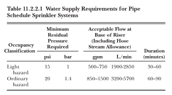
The pipe schedule discharge density is indirectly specified by the residual pressure required at the elevation of the highest sprinkler and the minimum flow at the base of the sprinkler riser. In other words, the acceptable flow at the base of riser must be achieved while also supplying the required residual pressure at the highest sprinkler. This table also assumes that the sprinkler system piping is sized along with the pipe schedule, which is just a maximum number of sprinkler heads permitted on certain pipe sizes. For a light hazard sprinkler system, this pipe schedule is given by Table 23.7.2.2.1 of NFPA 13, 2016 Edition, as seen below:
Figure 3: Light Hazard Sprinkler System Pipe Schedule
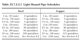
If you know the K factor of the sprinklers in the system, it is easy to determine the design discharge density. A sprinkler K factor is a measure of how much a sprinkler head discharges that is dependent upon the size of its discharge orifice and other discharge characteristics of the sprinkler head. The most common K factor used is 5.6. To convert a pipe schedule system to a design discharge density, you need to know the K factor, the discharge pressure, and the sprinkler coverage area. The sprinkler coverage area is the spacing of the sprinklers in all four directions. Thus, if the sprinklers are spaced 15 feet by 15 feet, the coverage area is 225 square feet. The formula to calculate flow from an individual sprinkler head is the K factor multiplied by the square root of its discharge pressure. So, the discharge density for our example above can be calculated as:
Flow = K factor x Pressure^1/2
Flow = 5.6 x 15^1/2 = 21.7 gpm
Discharge Density = Flow/Area = 21.7 gpm / 225 ft2 = 0.096 gpm/ft2
Control Mode Density Area
For Control Mode Density Area (CMDA) systems, the design discharge is obtained by researching the hazards in a specific facility, and choosing the appropriate density that applies to it. This is not a simple process, and should be determined by a qualified designer. Conventional sprinkler systems are classified into the following occupancy hazards: Light Hazard, Ordinary Hazard Groups 1 and 2, and Extra Hazard Groups 1 and 2. These hazards are listed in increasing order of hazard and discharge density. The discharge density is also determined by the design area of the sprinkler system, which is the largest hazard that is the farthest away from the water supply. The higher the design area is, the lower the design density is. Figure 11.2.3.1.1 of NFPA 13, 2016 Edition, is used to select a design discharge density based on these criteria, as seen below:
Figure 4: Design Density Curves
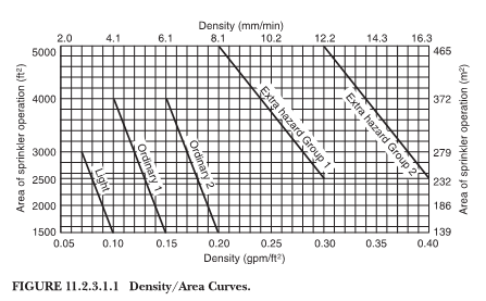
For example, an office building, which would most likely be classified as a light hazard sprinkler occupancy, a design density of 0.10 gpm/ft2 would be required over the most remote 1500 square feet. Unlike a Pipe Schedule System, a sprinkler system designer must perform hydraulic calculations to show that the water supply is adequate to provide the required discharge density. To this end, they must determine the minimum pressure required at the most remote sprinkler head to achieve this density. The formulas above for Flow and Discharge Density must be manipulated to calculate this pressure. For the same coverage area of 225 ft2 used above, and a sprinkler K factor of 5.6, the minimum pressure is:
Required Flow = Discharge Density x Area = 0.10 x 225 = 22.5 gpm
Required Pressure = ((Required Flow) / (K factor))^2 = 16.2 psi
Thus, for this example, the most remote sprinkler head (and all other sprinkler heads), must be supplied with a pressure of 16.2 psi or greater. The methodology of performing hydraulic calculations is detailed in NFPA 13, and is based on the Hazen-Williams pressure drop formula. The details of this procedure are complex and are typically performed by engineering technicians or engineers. However, the basic premise will be summarized here. The formula for the Hazen-Williams pressure drop equation is given in NFPA 13 as:
Figure 5: Hazen-Williams Pressure Drop Equation
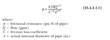
As seen from the equation, there are three factors that determine the pressure loss in a pipe or fitting:
- The flow
- The friction loss coefficient
- The internal diameter of the pipe
The friction loss coefficient is based on the piping material. Smoother materials, like plastic, have higher values and result in less friction loss. Fittings, valves, and components other than piping are assigned a length of piping that results in the same friction loss as if the components were straight lengths of pipe. The variable that affects friction loss the most is the piping diameter.
The discharge density outside of typical occupancy hazards as identified above, such as bulk storage or flammable liquids, depends on the materials stored, the material arrangement (height, spacing, etc.), and whether or not supplementary sprinklers are provided. An example of supplementary sprinklering would be in-rack sprinklers for rack storage, which are sections of sprinklers placed at intermediate rack levels. The discharge density for in-rack sprinklers are given by minimum pressures and K factors.
Control Mode Specific Application
CMSA are sprinklers that are specifically designed and tested to control bulk storage fires. They have larger water droplets than CMDA sprinklers and are used primarily to limit the spread of fire in storage warehouse applications. Unlike CMDA sprinklers, they do not have specific densities directly specified, although the densities can be calculated using the equations above. In order to protect a specific storage hazard, one must consider the storage material, the storage height, and the ceiling height. Using this information, the following design criteria are given by NFPA 13:
- The K factor
- The sprinkler head orientation, either upright or pendent
- If a wet or dry type system is being contemplated
- The number of design sprinklers flowing
- The minimum pressure at the sprinkler head
- Whether or not in-rack sprinklers are required
For the area of coverage for each sprinkler, its datasheet must be consulted. The datasheet will list the minimum and maximum areas of coverage for each sprinkler. An example of such a datasheet can be found here. Common coverage limits are 64 to 100 square feet per sprinkler. A specific example of how to determine the criteria is illustrated here by using Table 18.4(c) of NFPA 13:
Figure 6: CMSA Design Criteria for Rubber Tires
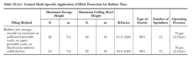
For the first row, with a K factor of 11.2, and operating pressure of 75 psi, and a coverage area of 100 square feet, the equivalent design density would be:
Density = K factor (75)^1/2 / 100 = 0.97 gpm/ft2
This value is way beyond the densities listed for Extra Hazard Group 2, and it is clear that the storage of rubber tires at such heights is very hazardous.
Early Suppression Fast Response
ESFR sprinklers are similar to CMSA sprinklers, except that they are designed to operate quickly and actually suppress the fire more so than just control it. These types of systems are newer than CMSA sprinklers and have become the gold standard for bulk storage hazards. They operate at lower pressures than CMSA sprinklers and often eliminate the need for in-rack sprinklers.
The criteria needed to select an ESFR design is identical to that of CMSA sprinklers. The requirements differ in that there are no dry ESFR systems. Thus, the criteria are:
- The K factor
- The sprinkler head orientation, either upright or pendent
- The number of design sprinklers flowing
- The minimum pressure at the sprinkler head
- Whether or not in-rack sprinklers are required
The area of coverage for ESFR sprinklers is generally between 64 to 144 square feet, with 100 square feet being the most common. Below is Table 16.2.3.1 of NFPA 13 which lists arrangements that can be protected by ESFR systems matching the criteria:
Figure 7: ESFR Design Criteria for Rack Storage
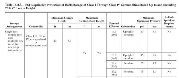
For the first row, with a K factor of 14, and operating pressure of 50 psi, and a coverage area of 100 square feet, the equivalent design density would be:
Density = K factor (50)^1/2 / 100 = 0.99 gpm/ft2
This density is similar to that of the CMSA example, being far higher than typical occupancies.
Conclusion
Design discharge densities of sprinkler systems are one of the most important criteria for designing sprinkler systems. While not covered here, classifying the sprinkler hazard occupancy or special occupancy is an essential exercise that is usually performed by an engineering technician or engineer. This classification is the first step taken before a design density is selected. A Fire Protection Engineer may be necessary for unusual or high hazard designs.
Except for CMDA systems, the design density is not directly prescribed; however, it is possible to calculate the discharge densities for the other types of systems. Pipe Schedule Systems are nearly obsolete, but an understanding of them is still necessary because these older systems may be encountered. CMSA and ESFR systems are mostly encountered in bulk storage buildings and warehouses, and specific information is needed in order to select the correct discharge characteristics, which are selected on the basis of different parameters than design discharge density.