Buildings and homes almost always have some sort of heating or air conditioning system installed within them to maintain a climate-controlled environment. Section 1203 of the 2018 International Building Code requires a heating system to be provided in order to maintain a temperature of 68 F 3 feet from the floor on the coldest design day. The exemption from this is for Group F, H, S, or U occupancies, which are industrial, high-hazard storage, and utility-type buildings. Even in buildings not required to have a heating system, the design of the HVAC system is usually similar to those that do. While most of us in the modern world consider air-conditioning (cooling) a necessity, it is not required for any building in the codes.
The main purposes of an HVAC system in a building are the following:
- To provide ventilation
- To provide heating
- To provide cooling
- To provide variable climate control
- To conserve energy
To these ends, we shall explore how these purposes are met in reality. This article provides an overview of the design process, but does not go into detail about such things as duct sizing, diffuser/grille selection, fuel gas pipe sizing, or control system details. This article is also geared towards commercial buildings, although residential systems are designed in the same way, but to different codes and standards and with fewer requirements.
Ventilation
What is ventilation? It is simply the movement of air outside to inside the building and vice versa. It is also called outside air, fresh air, exhaust air, and makeup air. Residential homes do not have ventilation requirements, presumably because there are always openable windows occupants can use to intake fresh air from the outside. The exception to this is for bathrooms, which must have an exhaust fan, unless there is an operable window within them. Adequate fresh air inside a building is essential for the health and well-being of its occupants. It prevents the build-up of carbon dioxide, contaminants, mold, and other irritants that are harmful to both healthy and respiratory-comprised occupants. From a more technical standpoint, the amount of fresh air needed in a building largely impacts the sizing of HVAC equipment, and subsequently, energy usage. There are several codes and standards that dictate how a mechanical engineer must determine the correct amount of outside air, where exhaust systems need to be located, and when energy recovery systems are needed to capture otherwise wasted energy.
The most common codes and standards used to calculate ventilation requirements are the International Mechanical Code (IMC), The Uniform Mechanical Code (UMC), and ASHRAE 62. The IMC is the most common code used for this, as it is the predominant mechanical code across the US. The UMC is more popular on the West Coast. ASHRAE 62 is used as an alternative to these codes, as it is permitted in the IMC and UMC. For this article, the IMC will be used as a reference, but the other standards are similar in scope and application.
Like homes, openable windows and other openings are permitted to supply so called “natural ventilation” if their areas are large enough. Most commercial buildings rely on “mechanical ventilation,” where the HVAC system pulls the outside air in, conditions it, mixes it with return air, and then distributes it throughout the building through the ductwork supply system. Exceptions exist when engineered systems are able to treat return air to a degree of quality close to fresh air. The amount of fresh air required in a building depends on:
- Type of space or occupancy being considered
- The number of people within the occupancy or space
- Whether or not an exhaust system is required or installed
The IMC specifies specific spaces that need to be exhausted, such as commercial kitchens, bathrooms, garages, and laboratories. Table 403.3.1.1 of the IMC directly specifies the factors that need to be considered to calculate the minimum ventilation rates. An excerpt is found below in Figure 1:
Figure 1: Cropped Table 403.3.1.1 of the 2018 IMC
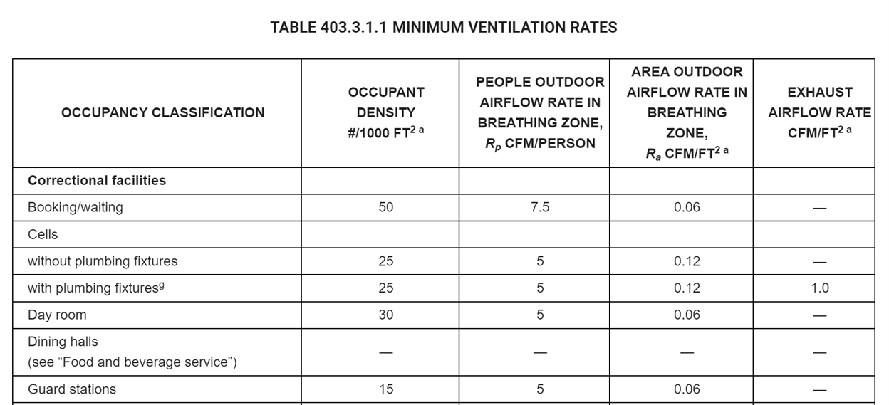
The second column of this table specifies the occupant density, which is just a way of calculating how many people are in a given space. The second prescribes an airflow rate required for each occupant. The third gives a general airflow rate based on the area of the space. The fourth, when present, indicates that an exhaust system is required and gives a value that needs to be multiplied by the area of the space to determine the exhaust airflow rate. The first three columns are combined into an equation to yield the overall outside air that needs to be delivered to the space. The exhaust airflow rate is determined simply by multiplying the factor by the area of the space that needs to be exhausted.
As an example to show how outside air is calculated for a space, consider the Booking/waiting room listed above in Table 403.3.1.1. Assume the space is 500 square feet. The first thing that needs to be done is to calculate the number of occupants based on column 1. To do this, take the occupant factor, 50, divide it by 1000, and then multiply it by 500. Thus, the number of occupants in the space is 25. Next, take 0.06 from column 3 and multiply it by the 500 square foot area for a value of 30 CFM. Finally, the number of occupants, 30, needs to be multiplied by the value in column 2, 7.5 CFM, and added to the 30 CFM previously calculated. The final value is 218 CFM. The HVAC system serving this space needs to deliver 218 CFM of outside air, which would be mixed with return air to provide the total supply air of the space. The outside air is normally lower than the total supply air, but sometimes they may be equal.
Heating and Cooling
The IMC requires that heating and cooling load calculations be performed using an approved procedure or via the standard ASHRAE 183. These calculations are complex, and are almost always performed by approved software. The heating and cooling load is the amount of energy delivered or extracted during a certain time that is required to properly heat or cool the building during specified times. Heating and cooling load calculations must consider the following, at a minimum:
- The ventilation or outside delivered into the building
- The exhaust air expelled from the building
- The number of people in the building[1]
- The area and volume of each space in the building
- The insulation encapsulating each room of the building, including the roof
- The location of the building
- The orientation of the building with respect to True North
- The coldest and warmest days of the year
- The coldest and warmest times of the day during the coldest and warmest days of the year
- The heat generated by various electrical and gas appliances
- The orientation and geometry of air supply diffusers and return grilles
- The number and size of doors and windows
- The insulation of doors and windows
There are other factors that may be considered that are not mentioned here. Heating loads are expressed in BTUs per hour. One BTU is the amount of energy required to heat one pound of water one degree Fahrenheit. It is important to note that the heating load is not just BTUs; it is a rate of energy that needs to be delivered; therefore, it is the amount of energy per unit of time (per hour) as btu per hour or btuh.
Cooling loads are expressed in “tons.” The unit “ton” was originally defined by the energy rate required to melt or freeze a ton of ice/water in 24 hours. This is an easy number to calculate. The heat of fusion of water/ice is 144 btu/lb. A short ton is 2000 pounds. The energy required to melt this amount of ice is the product of these two numbers, or 288,000 BTUs (not btu/hr). To convert this number to a cooling rate, simply divide it by 24 hours (recalling the definition of a ton above). The result is 12,000 btu/h. Many people state that a ton of cooling is simply 12,000 btu/hr, which is true, but this is just a conversion of the above, and is not truly what a ton of cooling actually is.
HVAC Equipment selection
Once these heating and cooling loads are determined, the HVAC equipment can be sized and selected. This is not an easy process, as there are many factors and considerations that need to be made. The size of the equipment is an easy thing to select; however, the system type and its location is difficult to determine. While the mechanical engineer has input on this decision and can provide recommendations, the system types are often selected by the owner and the architect. This is due to the overall geometry and function of the building. One of the most confusing aspects of HVAC design is the number and types of systems that are commercially available. Figure 2 below shows a central heating system within a small building. A burner is shown, but this system could easily be equipped with an air conditioning coil and outside condenser to deliver cooling as well.
Figure 2: Simple Central Heating System with Furnace
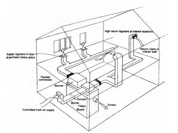
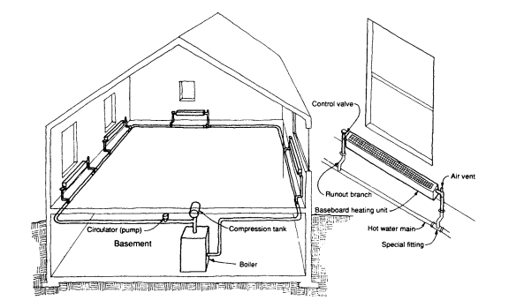
Figure 3 below shows another simple system, a one pipe hydronic heating system that could be connected to radiators or baseboard convection boards.
Figure 3: Single Pipe Hydronic Heating System
The heating and cooling systems used for larger buildings are more complex, and will not be illustrated here. Also, within a building, there may be multiple heating and cooling units. Units, or portions thereof distribute heating or cooling to different “thermal zones.” Thermal zones are parts of buildings that have similar heating or cooling demands, based on their locations, loads, or other factors. Each thermal zone is controlled by at least one thermostat. Most people are familiar with thermostats, as they are present in any home with a heating or cooling system.
Some examples of different heating and cooling systems are as follows (and this is far from a complete list):
- Mini and full split systems with furnace/coil and condenser inside and outside, respectively
- Boiler systems that use hot water to heat coils or other components that deliver hot air to spaces
- Chillers, which are large pieces of equipment that cool water, that deliver cool water to fans or coils that blow cold air into the building
- Completely packaged units located outside of the building, often on rooftops, and both cool and heat air directly from supply and return ducts connected to them
- Evaporative cooling units that utilize the cooling effect of water evaporating to cool air
Controls and Energy Conservation
A control system for an HVAC system can be as simple as one thermostat. A thermostat is basically a thermometer that sends an on/off control signal to a furnace or air conditioning unit when a certain temperature is low or high enough, respectively. Control systems for large, more complex systems integrate an array of electronics, sensors, and pre-programmed data to efficiently heat and cool buildings. These controls also activate certain equipment that is used for energy conservation.
Buildings and building systems are regulated as to how much energy they are permitted to use. The most common code regulating such energy usage is the International Energy Conservation Code. Within this code, there are efficiency requirements for equipment, and provisions for when certain energy recovery systems are needed. For example, a furnace using natural gas may require an efficiency factor of 0.8. This means the furnace must deliver 80% of useful heating with respect to the energy of the gas supplied to it. So a furnace with a 100,000 btu/h input capacity must be able to deliver 80,000 btu/h of useful energy.
The International Energy Code comes with a useful software tool referred to as a COMcheck. The designer inputs various energy efficiency inputs, and the software determines if the design meets the energy code. Many designers go far beyond the minimum energy requirements and use energy modeling tools to design even more energy-efficient systems. Over time, this saves the owner energy costs. Certain buildings are certified by the US Green Council as environmentally friendly to various levels. Ensuring the HVAC system is efficient is a part of this certification.
Conclusion
Preliminary design factors for HVAC systems were presented. After preliminary design, detailed engineering and design is necessary to design a full system. HVAC is a subdiscipline of the broadest field of engineering, mechanical engineering. HVAC systems have code requirements, but engineers use various approaches developed by themselves and other literature to design efficient HVAC systems that provide warmth and comfort to occupants. Improperly designed HVAC systems will inevitably be identified after the building is occupied, so it is imperative to design the systems properly.
John P. Stoppi Jr., PE, CMI is a mechanical engineer, mechanical inspector, and mechanical plans examiner. He has experience designing and inspecting residential and commercial HVAC systems.
[1] Surprisingly, the average person generates the same amount of heat as a 100 watt incandescent lightbulb, or 341 btu/h